OK this is the best I could do for today:
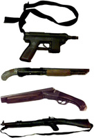
Summarized points:• Dylan’s body was found with his right hand over the GRIP of the Tec-9
• The Tec-9 was found with a loaded magazine and a live round in the chamber
• Dylan’s wound was NEAR CONTACT, through and through, slightly downward, and slightly front to back
• About 1” of drawback in the Tec-9 was traced Dylan
• A mix of blood in the trigger area of the Tec-9 was traced to mostly Eric, some Dylan
• Firearm discharge
[You must be registered and logged in to see this link.] is believed to be the bullet that killed Dylan – if so, it went through his head 36” above the ground (3 feet)
• DNA analysis on the bullet that killed Dylan was of no value
Dylan’s body position:1 - “KLEBOLD (
[You must be registered and logged in to see this link.]) [from Dr. Galloway] had a near contact wound to his left temple with a corresponding exit wound through his right temple. He also had aspirated blood. He could have been capable of some involuntary movement.” (JC-001-012309) (CBI Report, Team 2, page 12)
Note: “Near contact” means the gun was not touching his head when fired.
2 - “Body
[You must be registered and logged in to see this link.], DYLAN KLEBOLD… his right arm was extended by his side and his right hand was around the grip of the TEC-9 pistol.” (JC-001-012303) (CBI Report, Team 2, page 6)
3 - “A TEC-9 (Item
[You must be registered and logged in to see this link.]) with a live round in the chamber was in the right hand and under the right leg of KLEBOLD. It was also attached with a strap to KLEBOLD’S body. At 3:35 p.m. [April 21] under the direction of Jefferson County Coroner’s Office Chief Deputy Coroner Triena Harper, Hammond and Griffin cut the strap holding this firearm and removed it from KLEBOLD’s right hand.” (CBI report, Team 2, page 5)
4 - “There was a bloodstain area on the back of his left arm above the elbow that was not consistent with being formed with the arm in the position found. In addition, some of the blood flows on the face were also formed with the head in a position other than as found. These flows were consistent with KLEBOLDs head resting on the right side of the face to allow the blood flow on the left side out of the wound. There were bloodstains on his right bicep and left center portion of his neck.” (JC-001-012321, 012322)
DNA Profiles on the Tec-9:1 - “Areas of smudges and/or possible transfers are on the top, left and bottom of the [Tec-9] barrel. There was a flow pattern extending inside the barrel muzzle about 1 to ½ inches.” (CBI, Trace Arson page 3 of 77)
Note: What’s being referred to as a “flow pattern” is also called drawback, and is common for contact/close contact wounds. The person’s blood literally goes back into the barrel a short distance. DNA reports confirmed the drawback in the barrel of the TEC-9 was Dylan’s.
2 - “The DNA profiles developed from items
[You must be registered and logged in to see this link.] and 23C (Tec 9 pistol) matched the DNA profile from Klebold.” (CBI, DNA Reports, page 53)
Note: Area
[You must be registered and logged in to see this link.] is the inside of the barrel.
Eric’s blood in the trigger area of the Tec-9:1 - “The DNA profile from item
[You must be registered and logged in to see this link.] (Tec 9 pistol) revealed the presence of a mixture. The major component of the DNA profile from this mixture matched the DNA profile from Harris. The minor component of the DNA profile from this mixture was consistent with originating from Klebold.” (CBI, DNA Reports, page 53)
Note: Item
[You must be registered and logged in to see this link.] is the trigger area of the Tec-9 pistol. You can see the legend for areas
[You must be registered and logged in to see this link.], B, and C on page 6 of the CBI DNA Report.
[You must be registered and logged in to see this link.] is the outside of the barrel, B is the trigger area, and C is the inside of the barrel.
The bullet that killed Dylan and lack of DNA trace:1 - “Firearm discharge
[You must be registered and logged in to see this link.] was the 9mm projectile that killed KLEBOLD. The evidence recovered from discharges 13 and 14 may be the same as this event.” (JC-001-012316)
2 - “Firearm discharge
[You must be registered and logged in to see this link.] was the 9mm round (item 1124) that perforated the frame at the bottom of Window 6… this trajectory also passed over the area where KLEBOLD’s body was located at a height of approximately 36.” Of all the projectile holes/impacts in this area, discharge
[You must be registered and logged in to see this link.] was the most consistent (though not exclusively) with being the same as discharge
[You must be registered and logged in to see this link.] through KLEBOLD. (Note: DNA analysis on pellets and fragments recovered in this area did not have any evidentiary value.)” (JC-001-012317)
Note: If discharge
[You must be registered and logged in to see this link.] was the bullet that went through Dylan’s head as suggested, then it went through his head at 36” above the ground (3 feet).
Note: The live 9mm round that went through Dylan’s head (JCSO
[You must be registered and logged in to see this link.]/CBI
[You must be registered and logged in to see this link.]) was found to have “no value” by the corner. (CBI, Team 2, page 370 relative to the PDF file)
Note: Item
[You must be registered and logged in to see this link.] (9mm bullet that killed Dylan) was not traced to any specific gun. In the massive list of all shots fired and their origins in the CBI report, at the very end is a section listing 57 items that are labeled “Also Submitted” and were not traced to a specific weapon. Item
[You must be registered and logged in to see this link.] (the bullet that went through Dylan’s head) is among these items. (JC-001-012206)
Re: Sketches and diagramsThe two lab technicians who created the sketches and computerized diagrams were Tom Adair from the Arapahoe County Sheriff’s Office (Team One), and Laura DeLong from the Arapahoe County Sheriff’s Office (Team Two). Both were senior lab technicians.
The problem with looking at diagrams: When looking at a diagram that has an inaccurate detail, or a missing piece of evidence, it seems logical to conclude that a detective made a mistake. That’s not the case. Diagrams aren’t that simple. When you look at any diagram, what you’re looking at is not a finished product, but a piece out of an entire process that requires knowledge of the rest of the pieces to interpret correctly. Those pieces include all the other diagrams made by the field tech, including CAD documents and their field notes.
Yes, I am saying that you can’t interpret a single diagram without referencing all other diagrams and field notes. You can’t isolate a diagram from a lab tech’s field notes. If you do, you aren’t looking at the diagram in its proper context.
Diagrams go through a rigorous process to refine the accuracy of the details. Diagrams are also created for different purposes and will show different aspects of the crime scene and omit other aspects intentionally. Any given diagram you look at won’t be “complete” or accurate, not because “detectives messed up” but because the process of diagraming a crime scene isn’t a one-diagram process. Some diagrams are created to show only certain types of evidence (like shotgun-related evidence), or non-shotgun related evidence, or furniture, or just explosives. And what we have with the documents released from the Columbine investigation are not just final or selected diagrams. They released everything in-between. All the diagrams of the in-between stages that were in print format, that's what we've got. And many of them have inaccurate details including the location and angles of evidence, not because someone messed up, but because they're part of the diagraming process.
When you look at a diagram, you don’t know what you’re looking at unless you’ve got the tech’s field notes and have analyzed all other diagrams they’ve produced to see where the diagram you’re looking at fits in with their process.
Looking at a single diagram is looking at part of a process, but when you don’t understand the process, you think you’re looking at an end result.
After the initial sketch and walk through, diagrams are drawn and redrawn multiple times over and over again as the details are compared with other notes, photos, and videos of the scene. The lab techs who sketch and diagram a crime scene literally review each piece of evidence against photographic and video evidence to ensure they’ve positioned it correctly in their sketch. And it’s not always to scale. At least not until the end.
As the tech verifies each piece of evidence (which includes casings, fragments, burns, fibers, bodies, furniture, etc.), they redraw the diagram over and over and use symbols (their own legend) to indicate which items on that particular version of the diagram have been verified, moved, changed, or whatever. For example, Tom Griffin (one tech on the library team) used a triangle to indicate a fragment, a circle to indicate a live cartridge, a square to indicate a casing, and a half circle closed by a straight line to indicate a bomb fragment. That was his personal legend. Looking at his diagrams without knowing his legend would be confusing.
Similarly, as each new diagram is produced with more details that have been refined for accuracy, a tech will mark off the evidence they’ve verified. Specific to the library, Laura DeLong’s process was to go through and mark evidence numbers with an X or an O as she verified the position of 279 pieces of evidence against 1200 photographs (JC-001-012244). She created multiple diagrams in the process, and many of those diagrams were created with Auto CAD software, and we don’t know if we have all of her sketches.
While we can see a handful of different versions of diagrams created by DeLong, it’s clear that she’s marking off various pieces of evidence as she goes. Her notes also describe EXACTLY what she changes in the diagrams as she makes corrections and produces new versions of the diagrams. The changes include things like moving items, deleting duplicate evidence numbers, changing point layers, adding item numbers, and using symbols to more accurately locate evidence. For example, she duplicated evidence
[You must be registered and logged in to see this link.] and re-identified it as
[You must be registered and logged in to see this link.]. (Library Team 2, page JC-001-012736) There’s only one thing DeLong doesn’t change/correct in the diagrams – evidence around Eric and Dylan’s bodies.
The evidence around Eric and Dylan was not corrected due to space constraints on the diagram, according to DeLong. So when you look at a diagram that includes their bodies, there’s no way to know at what stage in the diagram process it was made, nor if it was before or after any corrections to the evidence found around and on their bodies.
We know Dylan was found with his hand around the grip – that was reported and recorded from the initial walk through.
Note that DeLong re-drew all the small sketches of chairs and table holes that were scattered through her notes, except for the chair by Dylan’s body. And some evidence numbers in certain revised sketches (evidence numbers that aren’t marked with an X) were not precisely measured and were placed relative to another object instead. (012753). This is normal! It’s part of the process. But you need to know how the process works to be able to know what you’re looking at before forming conclusions.
“The stacked evidence item numbers around the bodies of Klebold and Harris (B11 and B12) were pieces of clothing, evidence found within the clothing, or items of weaponry.” (012754)
(Side note: Dylan did not take off his jewelry and place it in a pile before he died, it was removed from his body and bagged up together - normal practice).
The original sketch made by DeLong can be found on page JC-001-012757 but the position of the Tec is unclear. Unfortunately, this sketch is the only original sketch released.
Another partially computerized sketch can be found on page JC-001-012800. It’s in this diagram that the position of the TEC is defined, but it’s not the final sketch fully verified against photos and other evidence. Here’s how I know this is not a final, fully verified sketch: you can see the “X”s on some evidence items (the X’s indicate verified evidence) and you can also see many evidence items without “X”s, which means, this is not a final sketch depicting a complete and verified crime scene. And since DeLong never placed “X”s on any of the evidence on or around Dylan and Eric’s bodies on purpose for space reasons, we will never know if the position of the TEC here was ever corrected. However, what we do know, based on Team Two’s findings, which are noted and cited in the beginning of this post, is that Dylan was found specifically with his right hand resting over the GRIP of the Tec-9. It’s not a red flag that the diagrams we have don’t match the position. When you understand the diagraming process, this becomes super clear.
DeLong explains that in early versions of her diagrams, she guestimated locations “pending further information from Adair (another senior lab technician from Team One), ” because coordinates were transposed (they use more than photographs to construct computerized diagrams to show where evidence was found – this leads to mistakes – it’s normal), and “mis-read information.” When these mistakes are discovered, they regenerate the diagram.
(For an example of this documented process, see page 001-012642 of Team 2) Keep scrolling for plenty of revision notes.
The first diagram DeLong created was just a basic layout of the room and position of furniture and bodies.
Through 4-28 to 6-25, DeLong added the locations of all the evidence to the diagrams. Then, on 5-12 and 6-3, she met with Tom Griffin at CBI to compare the photos of the scene to her notes to verify the positions of evidence.
On 6-29, DeLong met at the scene with others originally at the scene to discuss the correlation of evidence with witness statements. They viewed the photos again and compared them to the diagrams and the scene itself and she realized she needed to shift positions of chairs, rotate Eric Harris’ right foot, and add a few items of evidence. (012654).
Between 6-30 and 7-2, DeLong modified the diagram again as indicated in her report dated 6-30.
DeLong prepared multiple versions of diagrams for different purposes including:
Diagrams with only furniture
Diagrams with bodies
Shotgun related evidence items only
Non-shotgun ammo items of evidence including mixed and undetermined ammo
Diagrams with all evidence included
7 pages of detailed enlargements with furniture, bodies, and all evidence items
(JC-001-012655)
Knowing these are all the diagrams she created, it's actually quite clear that we do not have access to all the diagrams and they were probably mostly digital Auto CAD files and we got what was printed.
You need to know what diagram you’re looking at to form any kind of conclusion about what you think you’re seeing.
You also have to look at the evidence logs to see all evidence found around E&Ds bodies and where it was found precisely, since DeLong didn’t have enough room in the diagram to clarify corrections (as she noted). You can see more notes on their body positions (exact) on page JC-001-012703.
In the end, Team Two reported that Dylan's right hand was found around the grip of the Tec-9. That finding matches the photo that was leaked. And the leaked photo matches the description from the initial walk-through. So what part of the Tec Dylan was touching when he was found is pretty much off the table for debate.
“Body
[You must be registered and logged in to see this link.], DYLAN KLEBOLD… his right arm was extended by his side and his right hand was around the grip of the TEC-9 pistol.” (JC-001-012303) (CBI Report, Team 2, page 6)
**Edited to add, I just want to be clear that I am NOT saying I understand all the diagrams. I'm saying exactly the opposite - that everything is a complete clusterf** and we don't have any type of key or system or legend or list that tells us which diagrams we are looking at, what their context is, etc. Just field notes that are hardly legible, diagram after diagram with various details changed, the log of what was changed, but no way to know what diagram is relative to what changes. It could probably be pinpointed and checked off against the list of changes but who has time for that...